This project has been going on for more than a year now. Hopefully, this spring or summer, I'll have something that does what I want.
Features
Hopeful future features
I made a final prototype, putting into effect things I've learned from previous prototypes. I am trying a new hall effect sensor. The stock sensor uses an interrupter where the sensor and magnet are interrupted by the metal of the timing cup. The new sensor, which may not work, has the magnet and sensor in one unit. It was intended for gear teeth, but I'm hoping it'll detect the gap in the cup the same way. If that works, I may try two hall effect sensors, placed close together, to get more accurate crank timing.
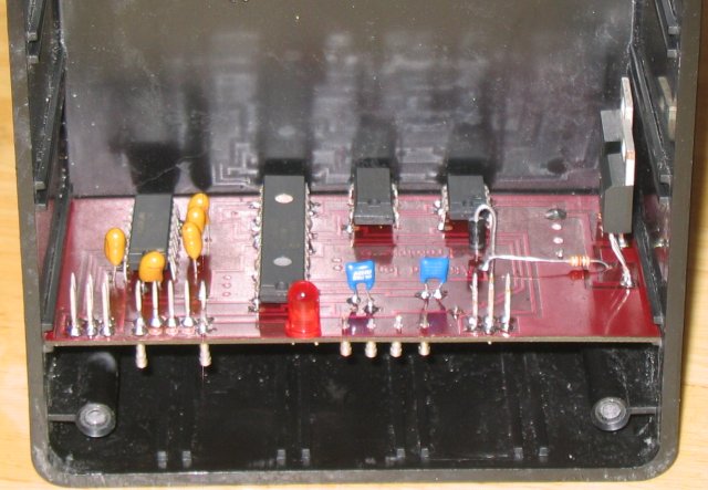
Here's a shot of the unit in my project box. This box is just small enough to fit under the seat.
On the right are the ignition and autoenrich transistors. The pins at the edge, just to the left of the transistors, are for connecting two digital sensors. One will be the hall effect sensor. The second will be the optical sensor that reads the encoder wheel. The next set of pins, to the left of the LED, are for connecting the programmer. The last set of pins are two RS-232 connections. The bits protruding from the bottom are wire plugs so I can connect wires by just pushing them in.
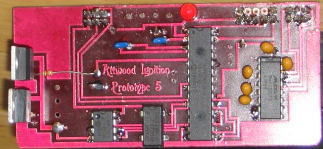
This is a top shot. From left to right, the chips are a 128Kbyte flash RAM, a 7.3728MHz clock ship, the microcontroller, and the RS-232 I/O chip.
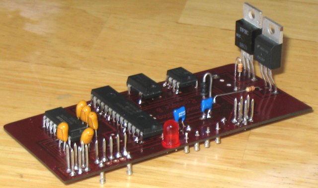
This is just another angle. Most of the smaller components, such as 5 volt regulator, capacitors, etc., are surface mount parts, placed on the bottom of the board.
Previously, I had connected the TPS the same way that the stock module does. On this unit, I'll have two Deutsch connectors, one to connect where the stock module connects, and the other to connect directly to the TPS/Autoenrich connector. Testing will begin during the next few days. I hope to connect it to the Blast by this weekend.